Regulated Car Battery Charger Circuit Diagram Pdf
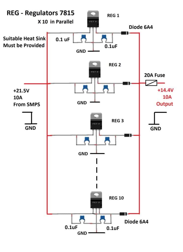
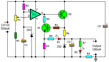
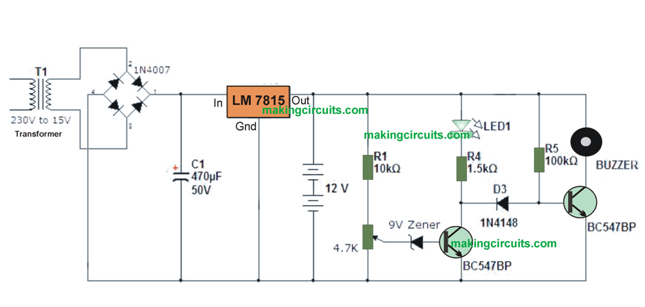
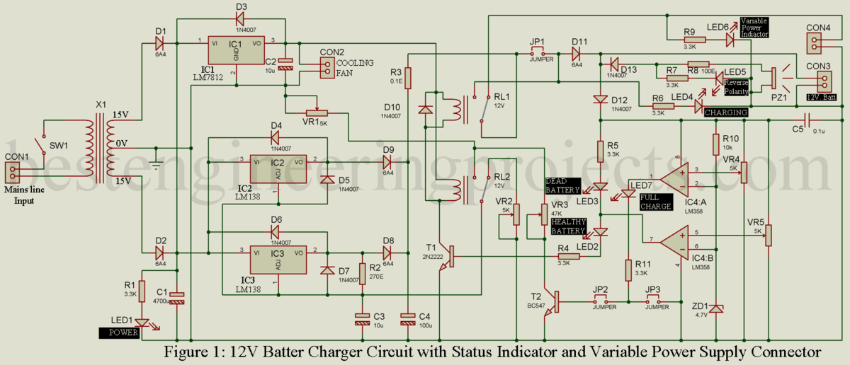
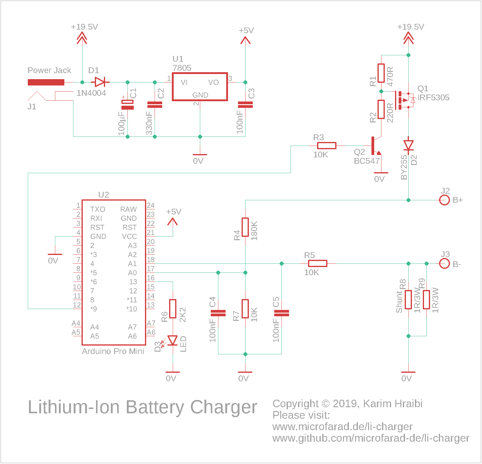
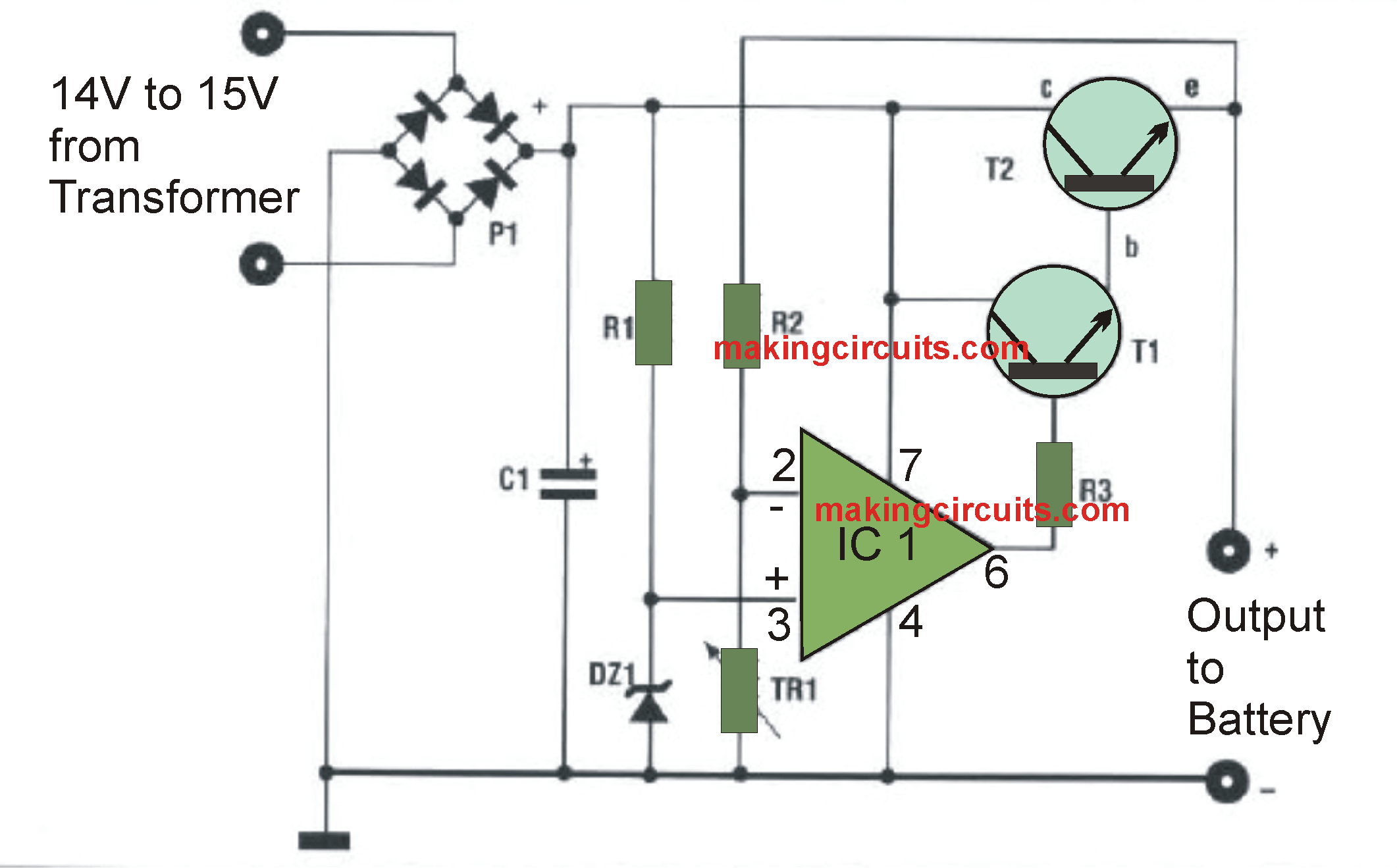
How the simple battery charger circuit works the charging circuit is created around voltage regulator ic 7815 and a couple of bc transistors 547 bjts.
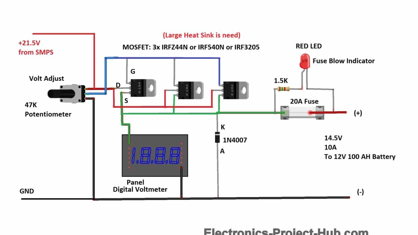
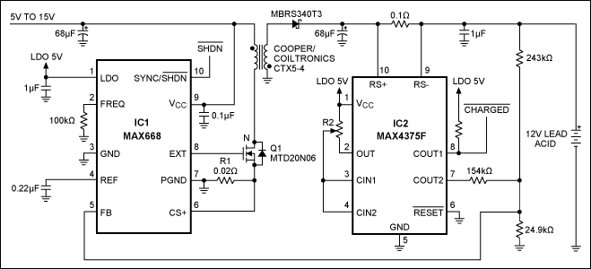
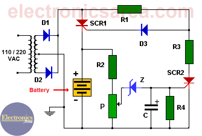
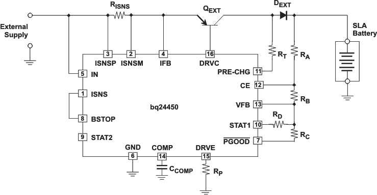
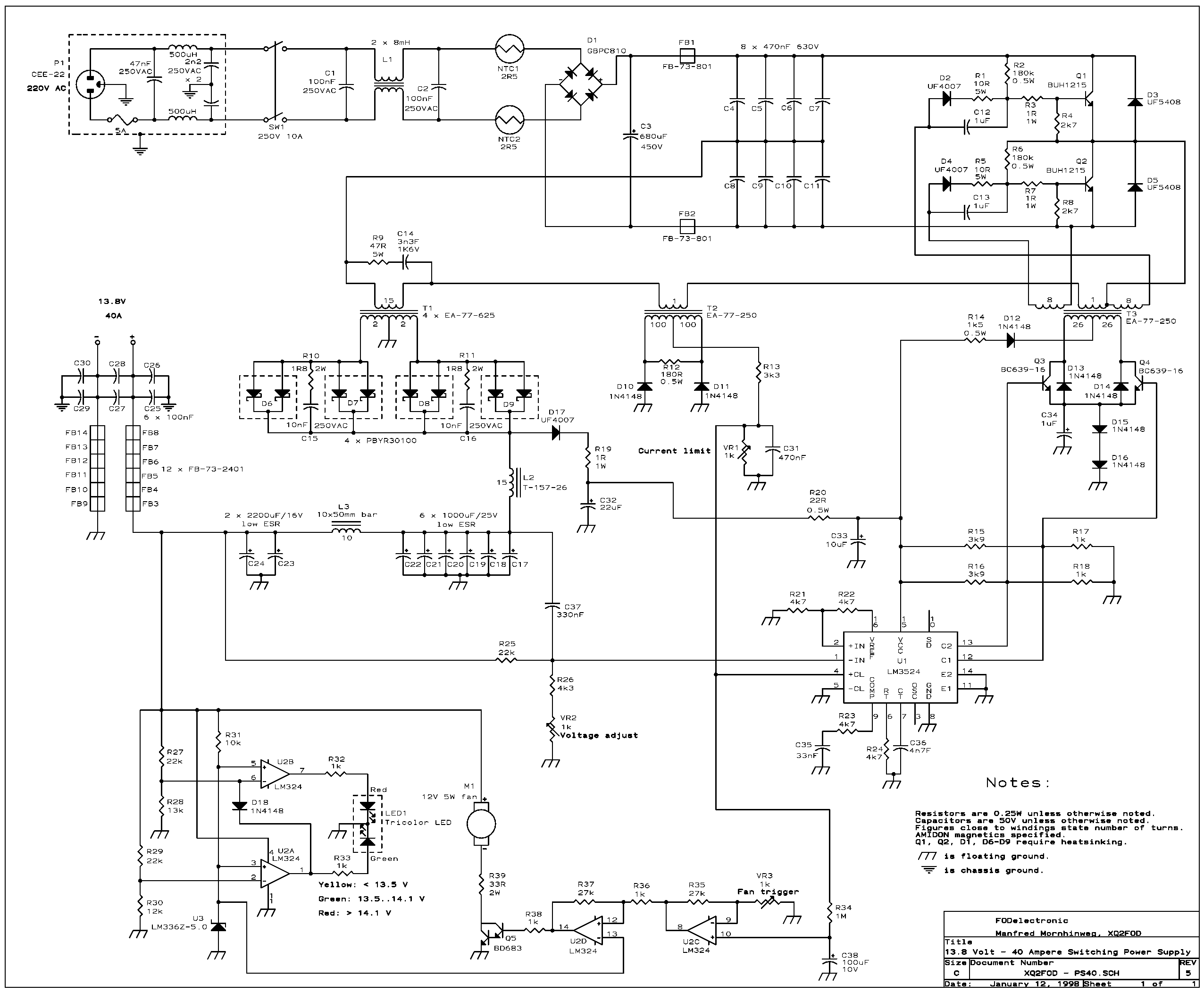
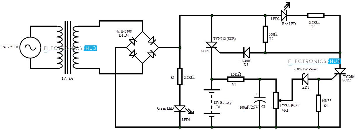
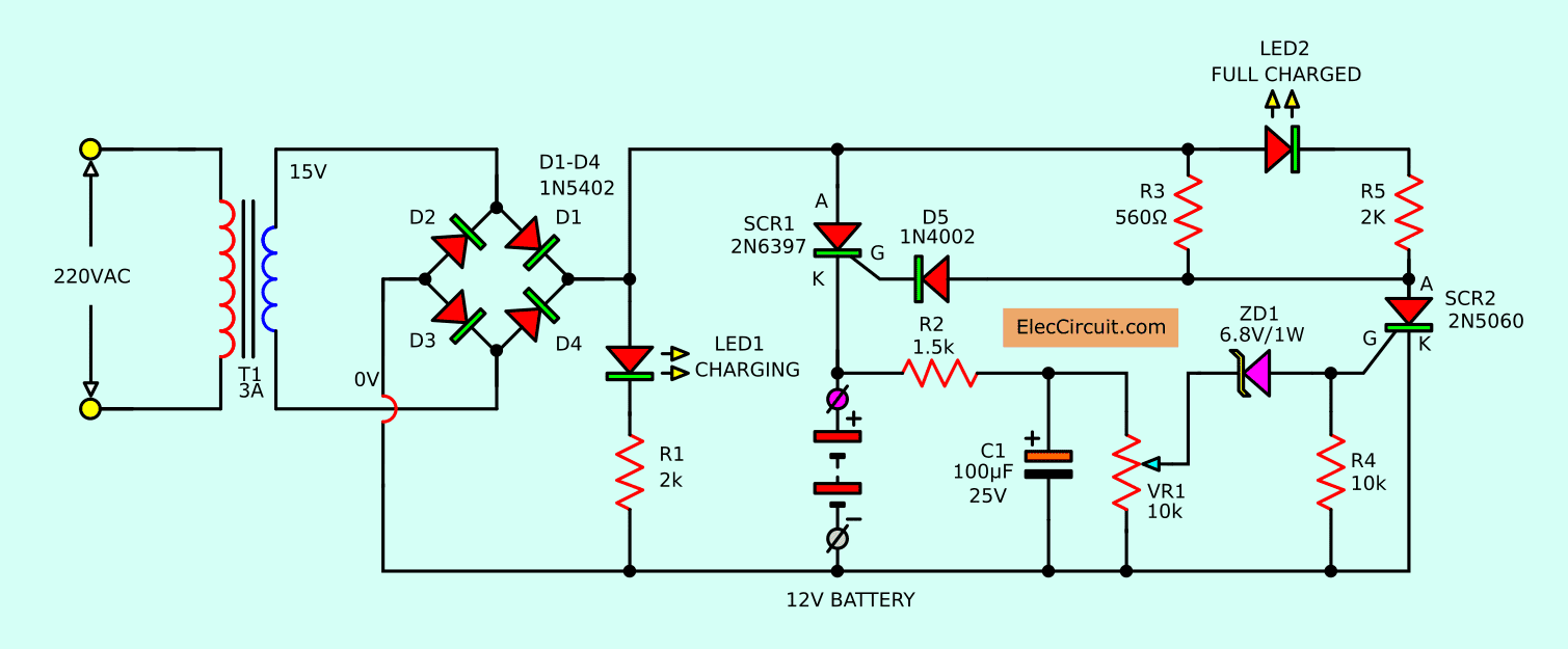
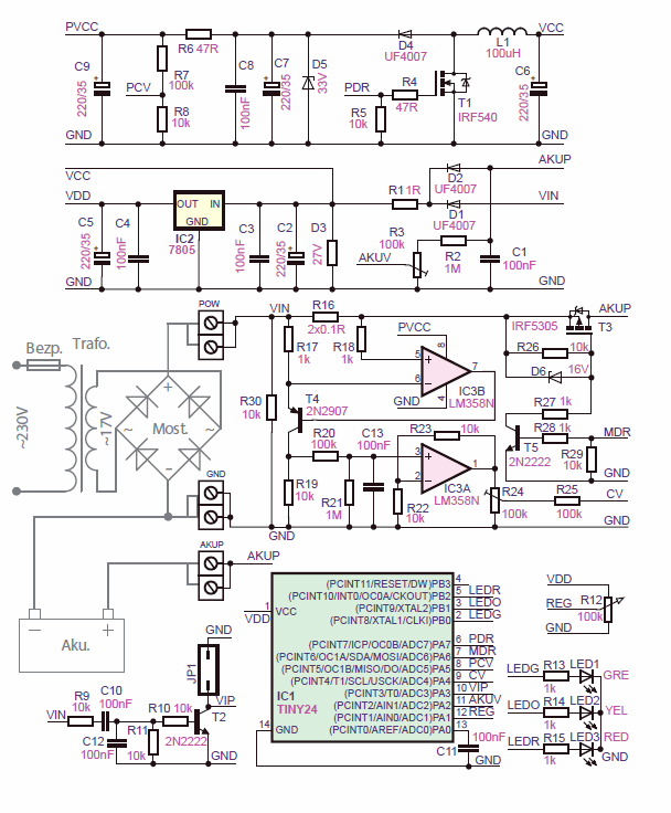
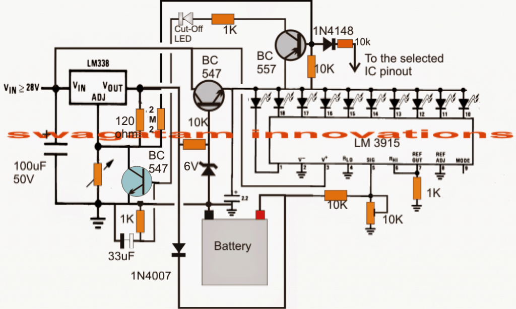
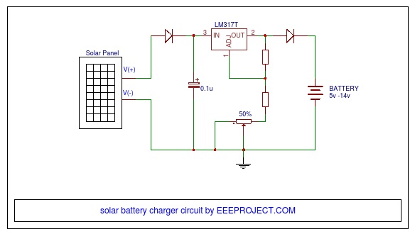
Regulated car battery charger circuit diagram pdf. Solar battery charger circuit principle. An automatic battery charger circuit using scr is implemented in this project. Regulated car battery charger circuit for garage mechanics last updated on february 10 2020 by swagatam 10 comments if you are an automotive technician vehicle technician or a motor mechanic you may find this cheap yet powerful car battery charger circuit extremely handy as it can be used for charging all types of car and motorcycle. Car battery charger circuit working principle.
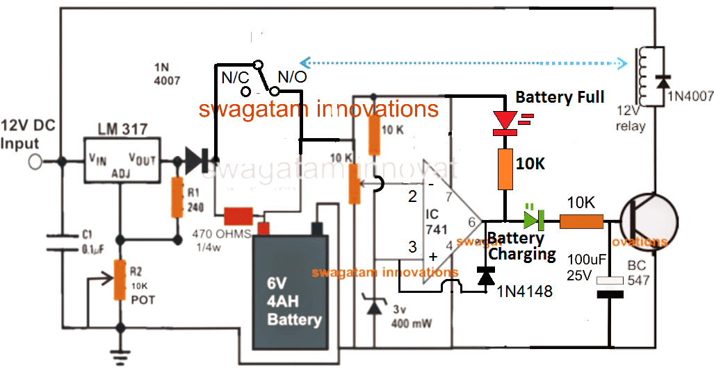
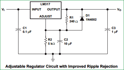
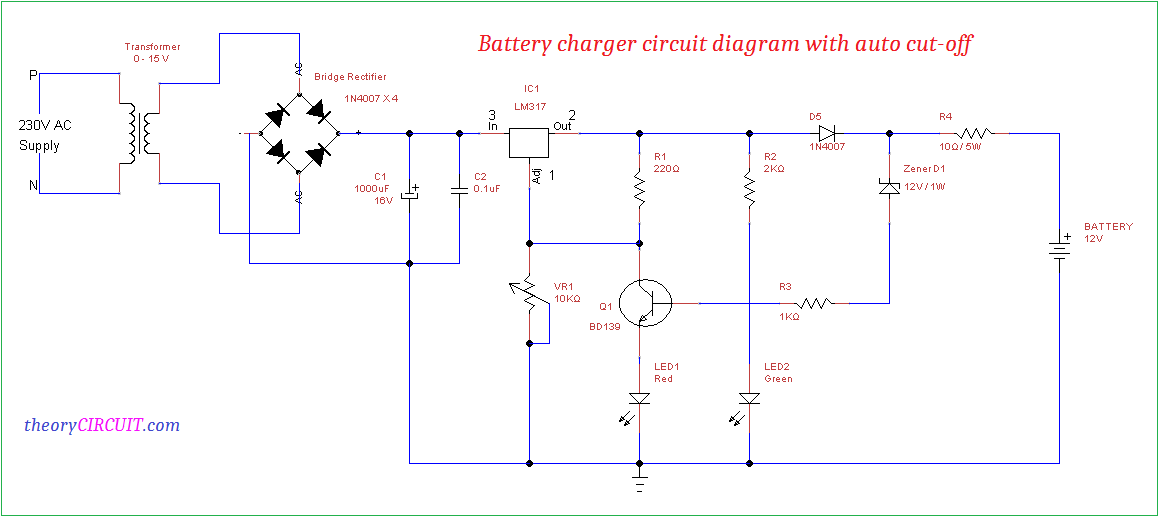
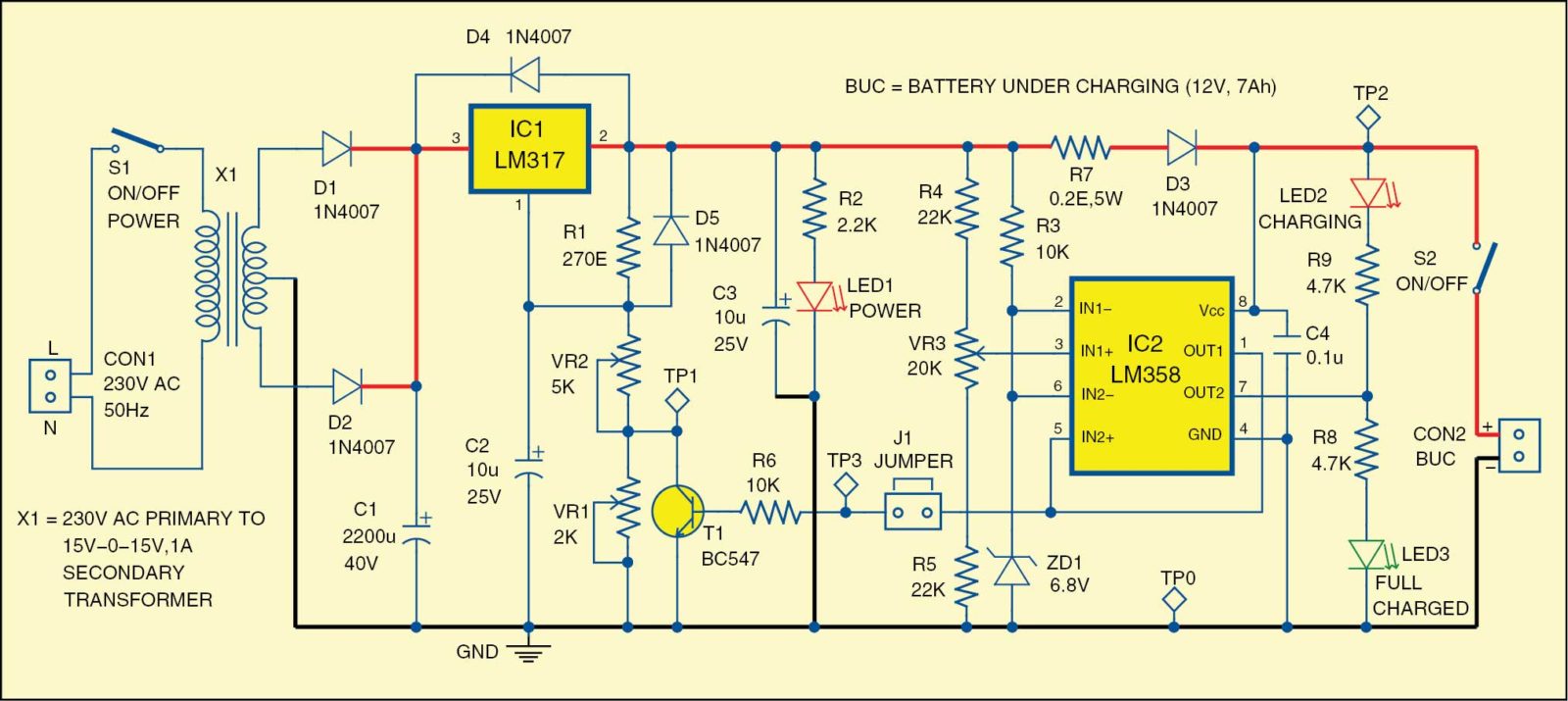
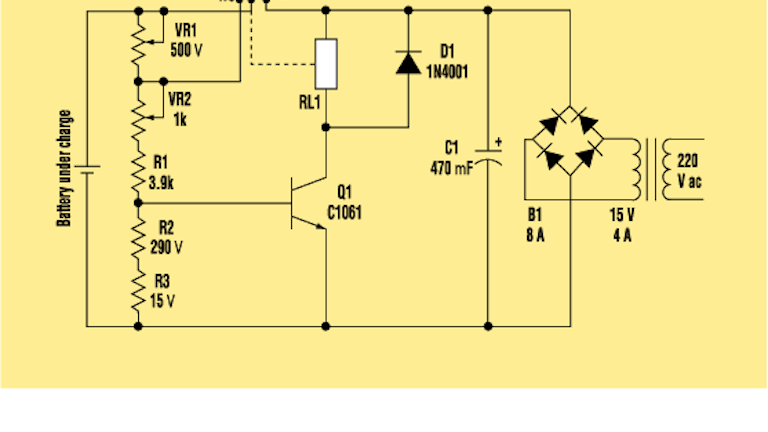
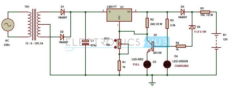
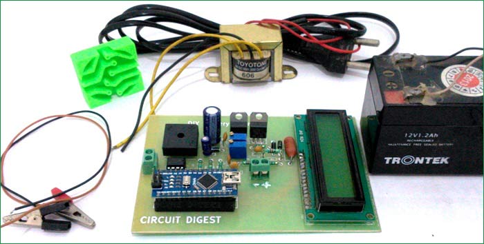
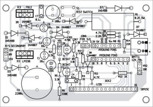
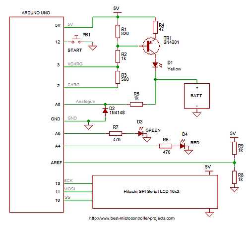
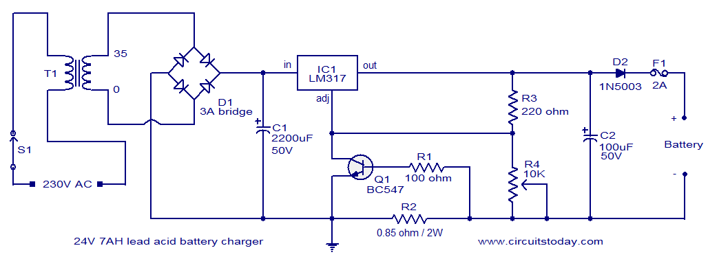
As the battery gets charged the terminal voltage begins increasing gradually until it reaches the set 142 v. As seen in the dc voltage is given to the dc voltage regulator here we use lm317 which is a dc voltage regulator. But our charger works on 12v hence with the help of a voltage divider circuit the value of 0 14 volt is mapped down to 0 5v using resistor r1 1k and r2 500r like have previously done in 0 24v 3a regulated power supply circuit to display the voltage on lcd using arduino nano. One 555 timer ic is used for detecting the voltage level and relay is used to disconnect the ac input.
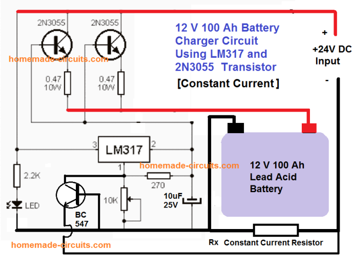
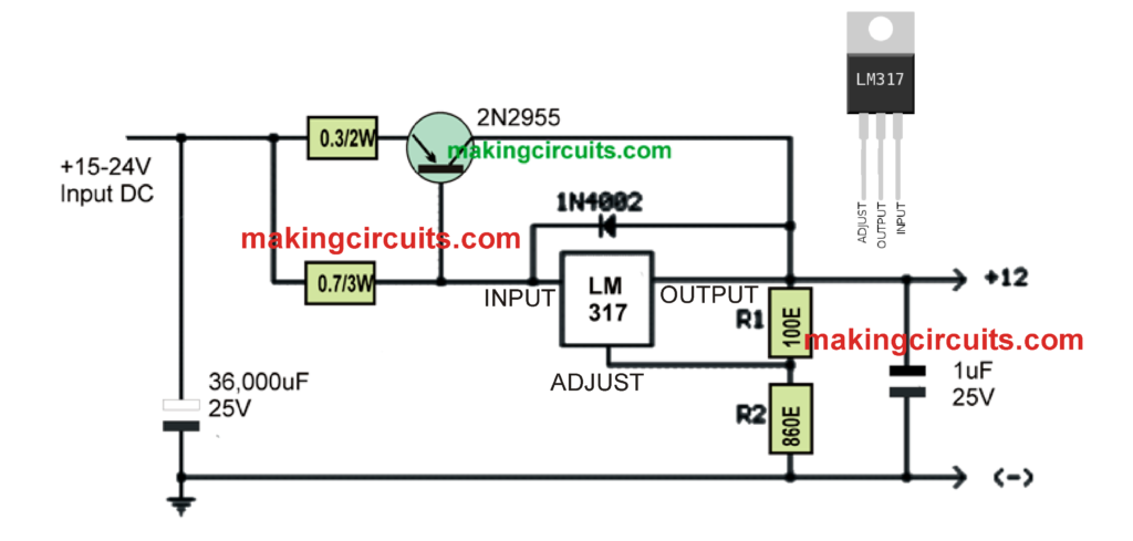
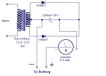
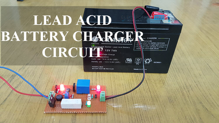
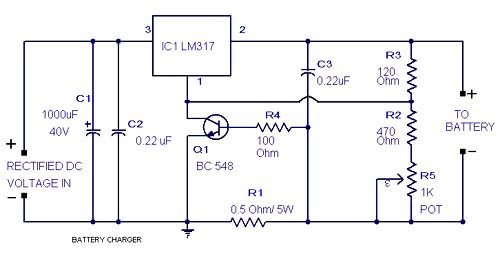
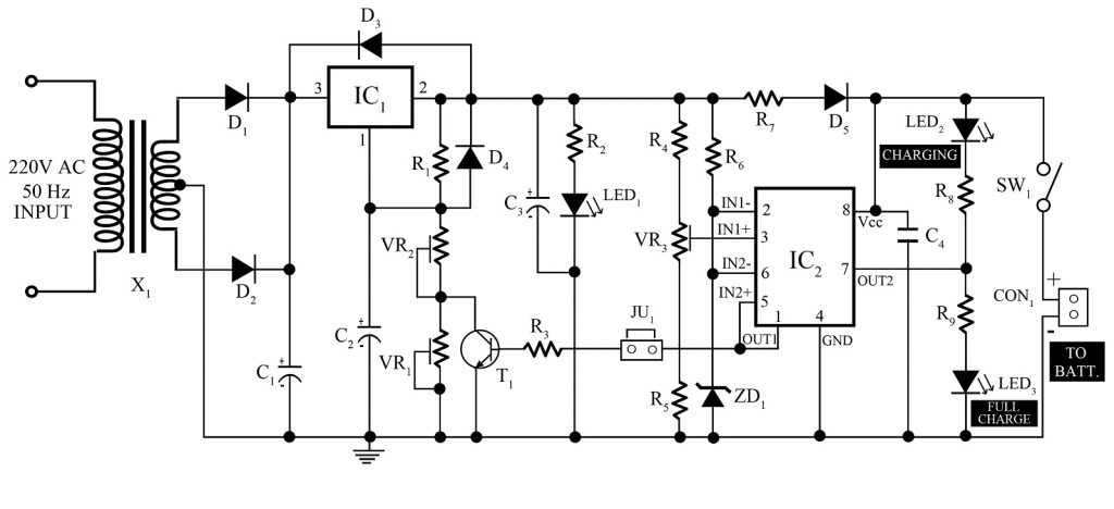
The main 230v or 110v input could be the first steped down through a step down transformer after that it may be rectified and filtered. Car battery is also a lead acid battery. This is a simple car battery charger with indication. The output voltage and current are regulated by adjusting the adjust pin of lm317 voltage regulator.
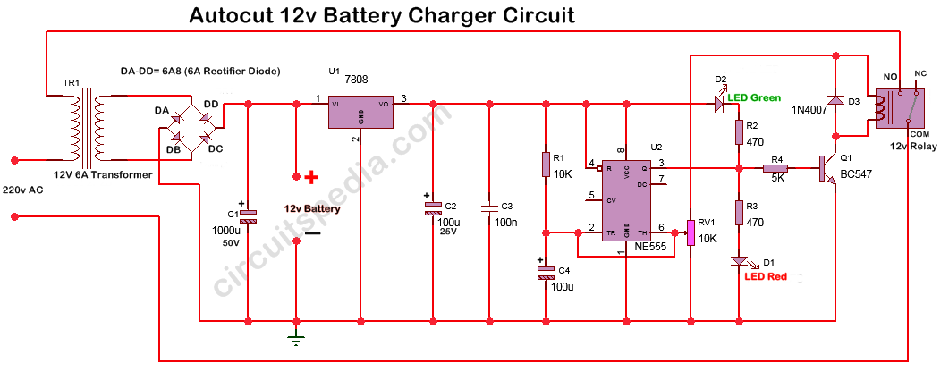
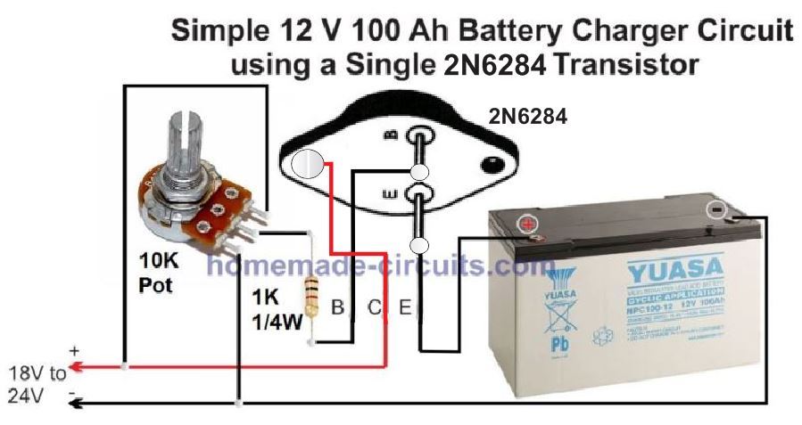
There is also a trickle charge mode circuitry which will help to reduce the current when the battery is fully charged. It can be used to charge 12v batteries. 7808 voltage regulator is used for constant supply to the operation of the circuit to cut at a required fixed voltage. A 12v battery is normally recharged at 142 v or 240v per cell.
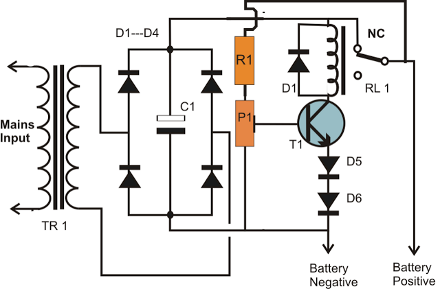
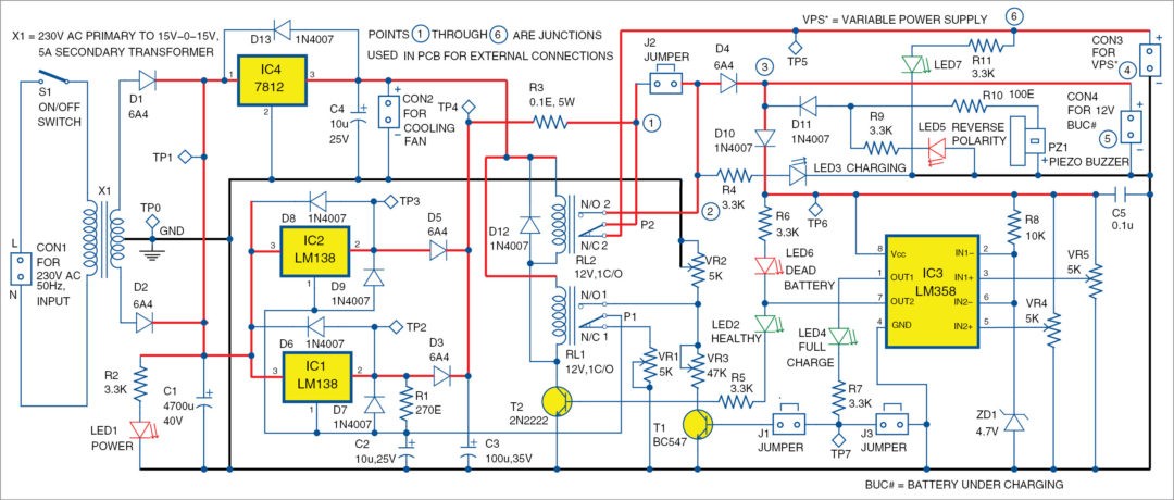
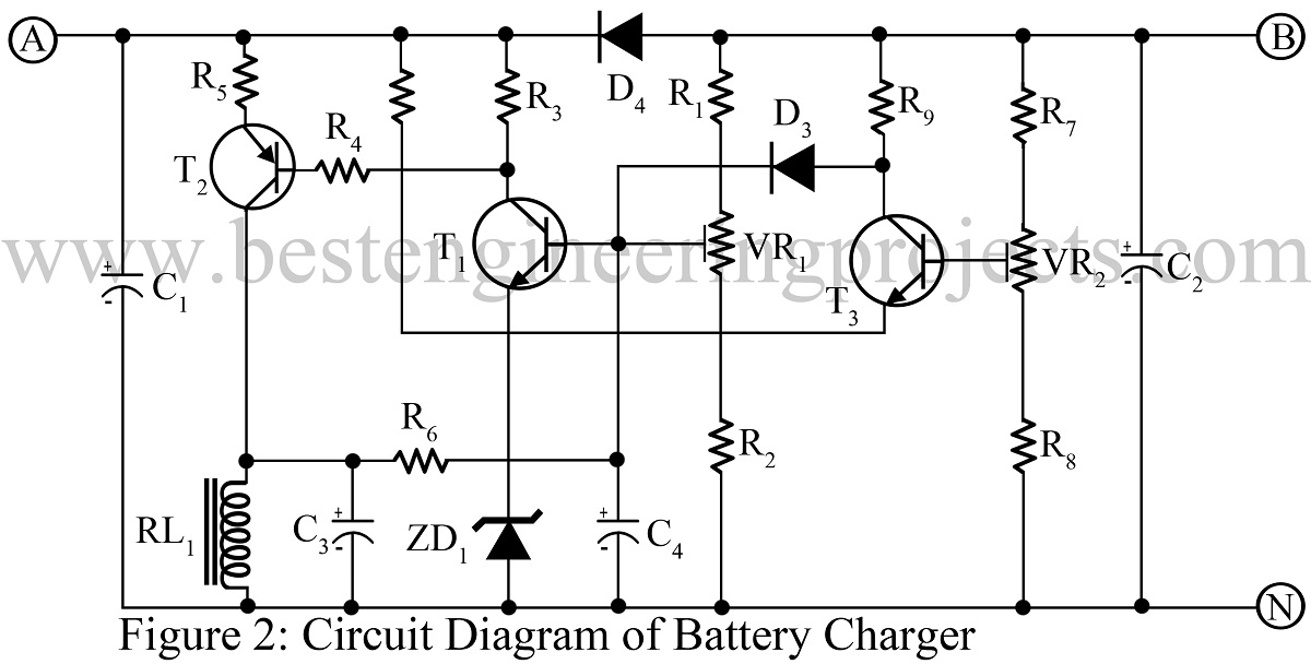
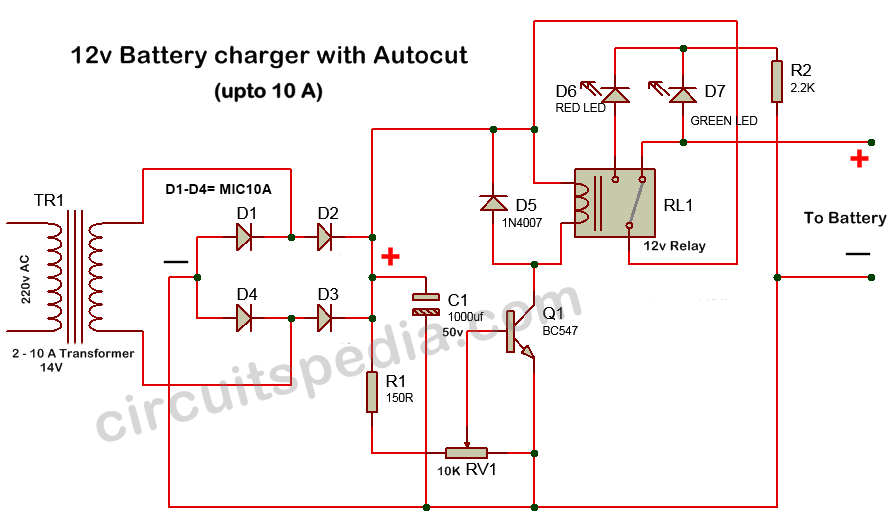
The working of the circuit is as. Related post lead acid battery charger using lm317 3battery charger using scr. The battery is charged from a 230v 50hz ac mains supply. Batteries with different potentials like 6v and 9v can also be charged by choosing appropriate components.
In the shown high current battery charger circuit using a voltage regulator the base of the transistor is fed with a regulated 15 v from the ic 7815 which ensures a potential difference of about 15 07 143 v across the emitterground of the transistor. This ac voltage is rectified and filtered to obtain an unregulated dc voltage used to charge the battery through a relay. Solar battery charger operated on the principle that the charge control circuit will produce the constant voltage. Once we attach the charger with the battery voltage drops from the actual supply 142 v level to the discharged level of the battery.
Https Encrypted Tbn0 Gstatic Com Images Q Tbn 3aand9gctwghdbiz61mnqbalgltuf5az1lgeb9fogwrh6yadm2fqcn9hxd Usqp Cau

